
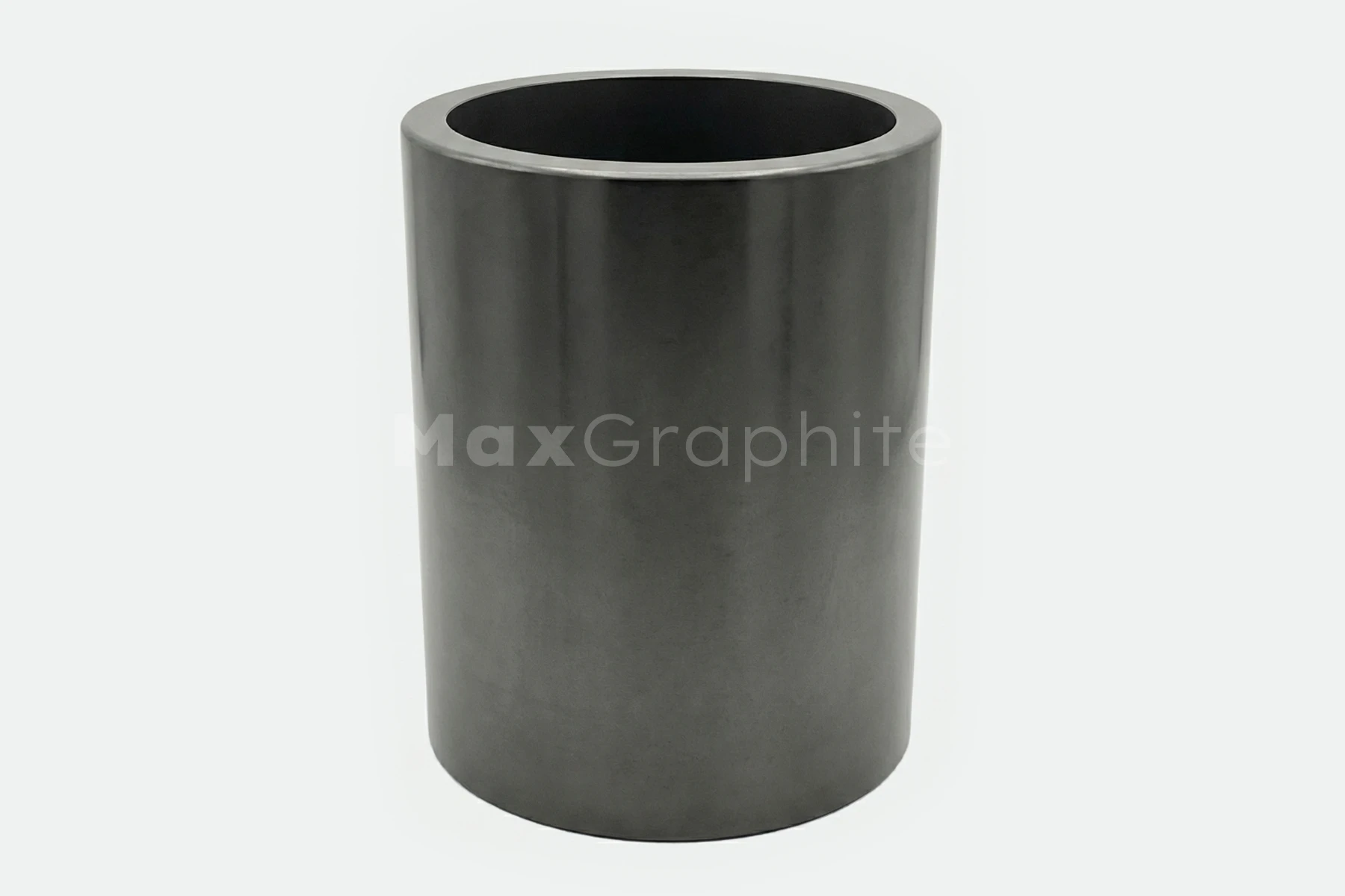
Carbon Carbon Composite
High-strength, lightweight composite engineered for structural integrity and thermal performance in the most demanding high-temperature applications.

Specification of
Carbon Carbon Composite
Max Graphite supplies C/C composite across a range of standard fiber architectures and density grades. Properties vary by fiber structure direction and densification method. The following table summarizes typical values by grade. All specifications can be tailored to application requirements.
Typical Grade Specifications: All values are typical; custom grades available on request.
Certifications:
Size of
Carbon Carbon Composite
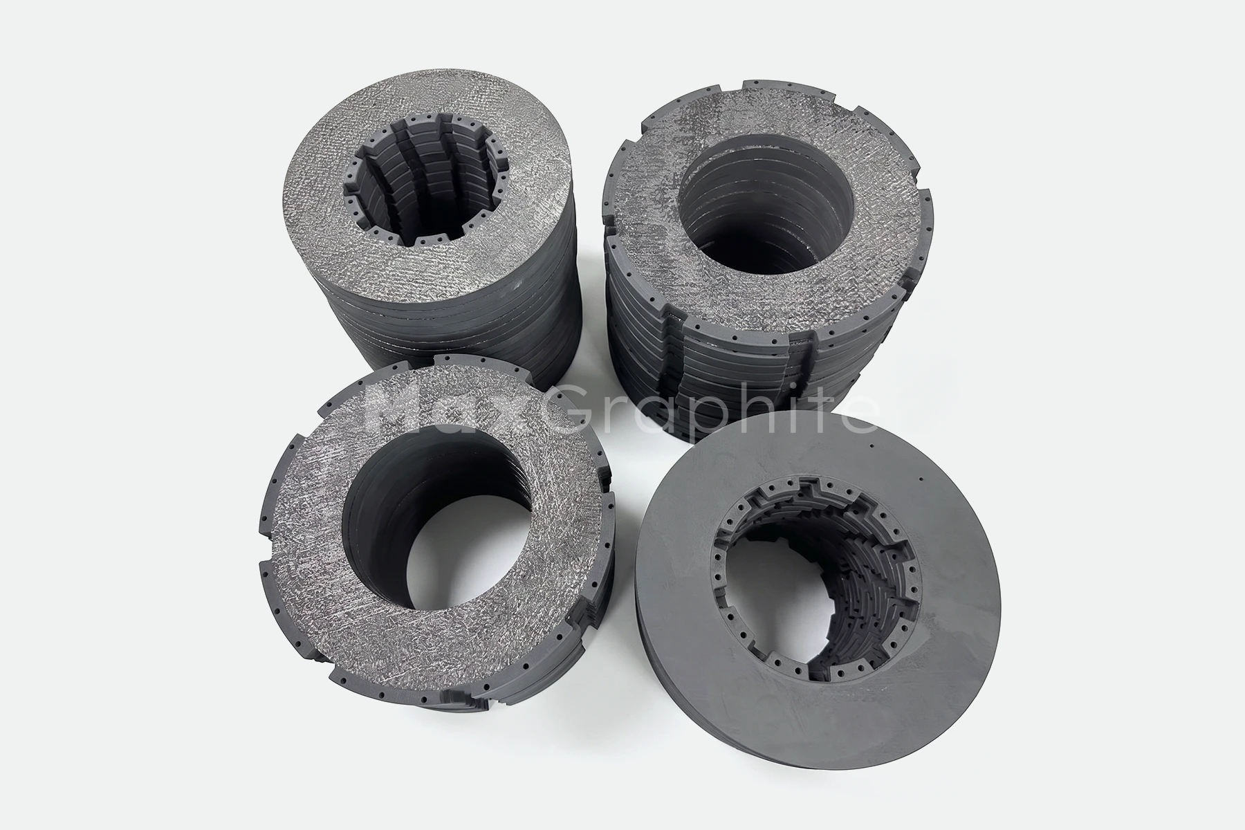
C/C composite components are custom-engineered to client specifications. Due to the fiber preform architecture, near-net-shape fabrication is standard practice — components are produced to closely match the final geometry, then precision-machined to final dimensions. There are no fixed stock dimensions.
Contact us for a detailed stock list or to discuss your custom size requirements.
What Is Carbon Fiber-Reinforced Carbon?
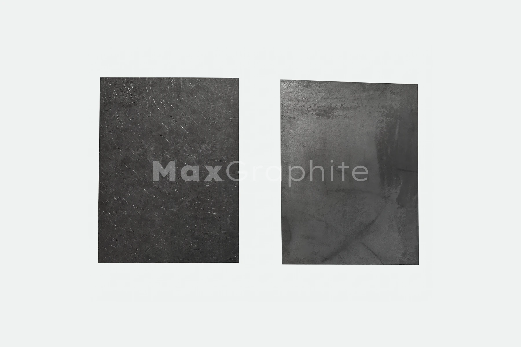
Carbon Fiber-Reinforced Carbon — interchangeably referred to as C/C composite, CFC, CFRC, or carbon-carbon composite — is a high-performance composite material consisting of carbon fiber reinforcementsbonded within a carbon or graphite matrix. Both the fiber and the matrix are carbon-based, making this an all-carbon system with carbon content typically exceeding 99% after graphitization.
Unlike polymer-matrix composites, C/C composite is not degraded by heat. Instead, it retains its structuralintegrity and, in many loading scenarios, gains strength as temperature rises. This thermally stable behavior is a direct result of the carbon fiber architecture — which can be engineered in 2D (planar), 2.5D, 3D (three-axis),or 4D/multidirectional configurations — and the densification of the carbon matrix through Chemical VaporInfiltration (CVI/CVD) or liquid-phase impregnation (pitch or resin) processes.
The material is fundamentally distinct from conventional carbon fiber composites used in aerospace structuralpanels or sporting goods. Those rely on polymer matrices and are limited to temperatures well below 300°C.C/C composite operates continuously in inert or vacuum atmospheres at temperatures exceeding 2500°C,making it irreplaceable in applications that combine structural load, thermal cycling, and chemical purity requirements.
Key Properties of Carbon Fiber-Reinforced Carbon
- Strength Retention at Ultra-High Temperatures — Unlike most materials, C/C composite maintains or improves mechanical properties up to 2500°C in non-oxidizing environments, making it uniquely suited to the most demanding thermal regimes.
- Outstanding Thermal Shock Resistance — The carbon fiber reinforcement arrests crack propagation and accommodates differential thermal expansion, allowing the material to survive rapid and repeated heating/cooling cycles without failure.
- Lightweight Construction — C/C composite components are significantly lighter than refractory metals and ceramics —reducing furnace load mass, improving thermal cycle efficiency, and enabling higher part densities per batch.
- Chemical Inertness — With >99% carbon content, C/C composite resists attack from acids, alkalis, and most corrosive media at elevated temperatures.
- Fiber ArchitectureFlexibility — Available in 2D, 2.5D, 3D, and 4D structures to optimize in-plane vs. through-thickness mechanical and thermal properties for specific loading conditions.
- Coating Compatibility — SiC, PyC (Pyrolytic Carbon), and other protectivecoatings can be applied to extend service life in oxidizing environments or toreduce surface porosity.

Production Process of Carbon Fiber-Reinforced Carbon
The performance characteristics of C/C composite are directly determined by a controlled, multi-stage manufacturing process. Each step contributes to the final fiber architecture, matrix density, and microstructural integrity of the component.
- Carbon Fiber Selection& Weaving — PAN-based or pitch-based carbon fibers are selected based on the required mechanical and thermal performance profile. Fibers are woven, braided, or laid up into a structural preform in the target architecture: 2D cloth lay-up, 2.5D needled felt, 3D orthogonal weave, 3D polar weave, or 4D/multidirectional weave.
- Preform Fabrication — The fiber preform is shaped to near-net geometry using tooling and fixturing, establishing the dimensional envelope and fiber volume fraction (typically 35–50%) of the final component.
- Matrix Densification viaCVI/CVD — The preform is placed in a chemical vapor infiltration reactor. Hydrocarbon gases (methane, propane)decompose at elevated temperature, depositing pyrolytic carbon within the open pore network of the fiber preform. This cycle may be repeated multiple times to achieve target density.
- Liquid PhaseImpregnation (Optional / Alternative) — Forcertain grades and geometries, the preform is impregnated with coal tar pitchor thermosetting resin under pressure, then carbonized. Thisimpregnation-carbonization cycle is repeated to progressively close porosityand increase density.
- Carbonization — Impregnated preforms are heat-treated at approximately900–1200°C in an inert atmosphere to carbonize the pitch or resin binder,converting it to amorphous carbon.
- Graphitization — For grades requiring maximum thermal conductivity andreduced electrical resistivity, the material is heated to approximately2500–2800°C, transforming amorphous carbon into a more ordered graphiticstructure.
- Densification Cycling — Steps 3–6 may be repeated multiple times until the targetbulk density is achieved. Higher densities (≥1.85 g/cm³) require more cyclesand longer processing times (typically 5–8 months for complex 3D/4D parts).
- Surface Coating(Optional) — SiC or PyC coatings areapplied via CVD to improve oxidation resistance, reduce surface porosity, ortailor friction and wear characteristics for tribological applications.
- Precision Machining& Quality Control — Final componentsare CNC-machined to customer drawings. Each part undergoes dimensionalinspection, density verification, and structural testing prior to dispatch.
Applications
HeatTreatment & Vacuum Furnace Equipment: Fixtures, trays, setter plates,heating elements, and hot zone structural components that must withstandrepeated thermal cycling at temperatures above 1200°C while maintainingdimensional stability and minimizing contamination of processed parts.
SemiconductorManufacturing: Susceptors, wafer carriers, andprocess chamber components requiring ultra-high purity, dimensional stabilityat process temperatures, and resistance to halogen-containing atmospheresencountered in silicon and SiC crystal growth.
Aerospace& Defense Structures: Rocket nozzles, re-entry vehiclethermal protection components, leading edge structures, and solid rocket motorcomponents — where high structural strength, minimal component mass, andablation resistance under extreme thermal flux are mission-critical.
Aircraft& Industrial Brake Systems: Brake discs for commercial andmilitary aircraft, and industrial braking systems, leveraging C/C composite'ssuperior friction and wear characteristics, weight savings versus steel, andability to operate effectively through repeated high-energy braking events.
Solar& PV Crystal Growth: Crucible susceptors, heatercomponents, and structural supports in Czochralski and directionalsolidification furnaces for silicon and sapphire ingot growth, where highthermal conductivity, purity, and resistance to thermal cycling are essential.
ContinuousCasting & Metallurgical Processing: Casting dies, nozzles, and moldcomponents that benefit from C/C composite's non-wetting behavior with moltenmetals, high thermal shock resistance, and dimensional stability.
MechanicalEngineering & Precision Tooling: Springs, press tooling, andstructural members in high-temperature mechanical systems where theself-lubricating surface character and high specific stiffness of C/C compositeoffer advantages over metallic alternatives.
Related Materials and Products
Isostatic Graphite
2.5D CFC Carbon-Carbon Composite
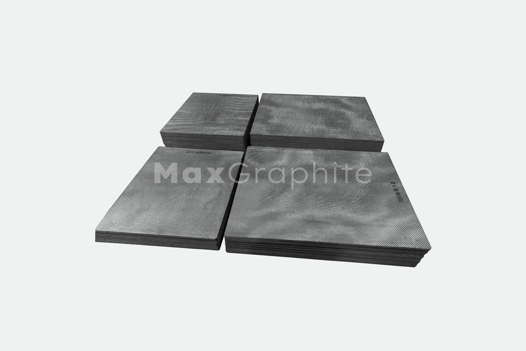
2D CFC Carbon/Carbon Composite
3D & 4D CFC Carbon Composite
Short Fiber (Random Fiber) CFC – Carbon/Carbon Composite

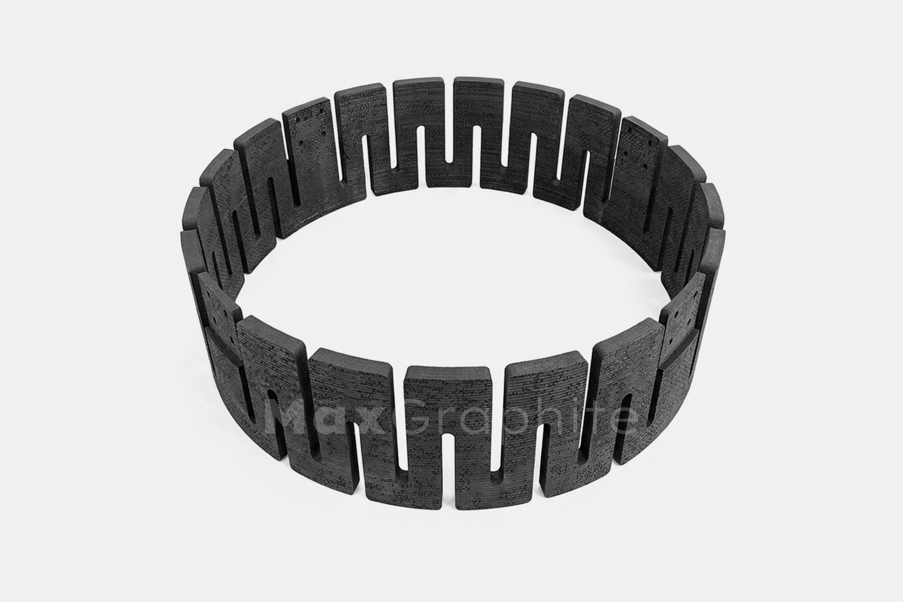
Carbon/Carbon Loading Racks for Heat Treatment
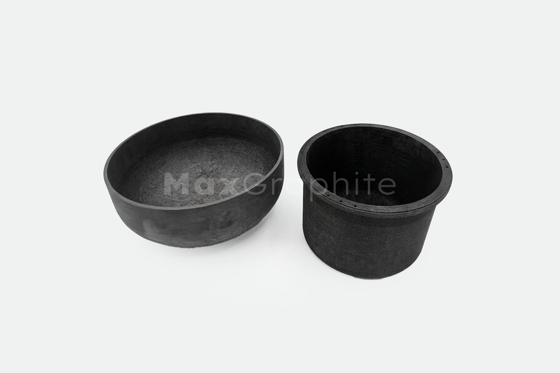
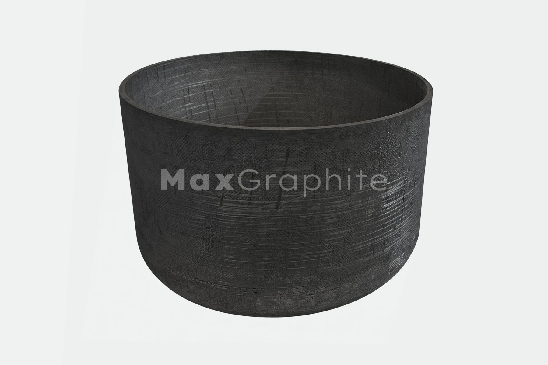
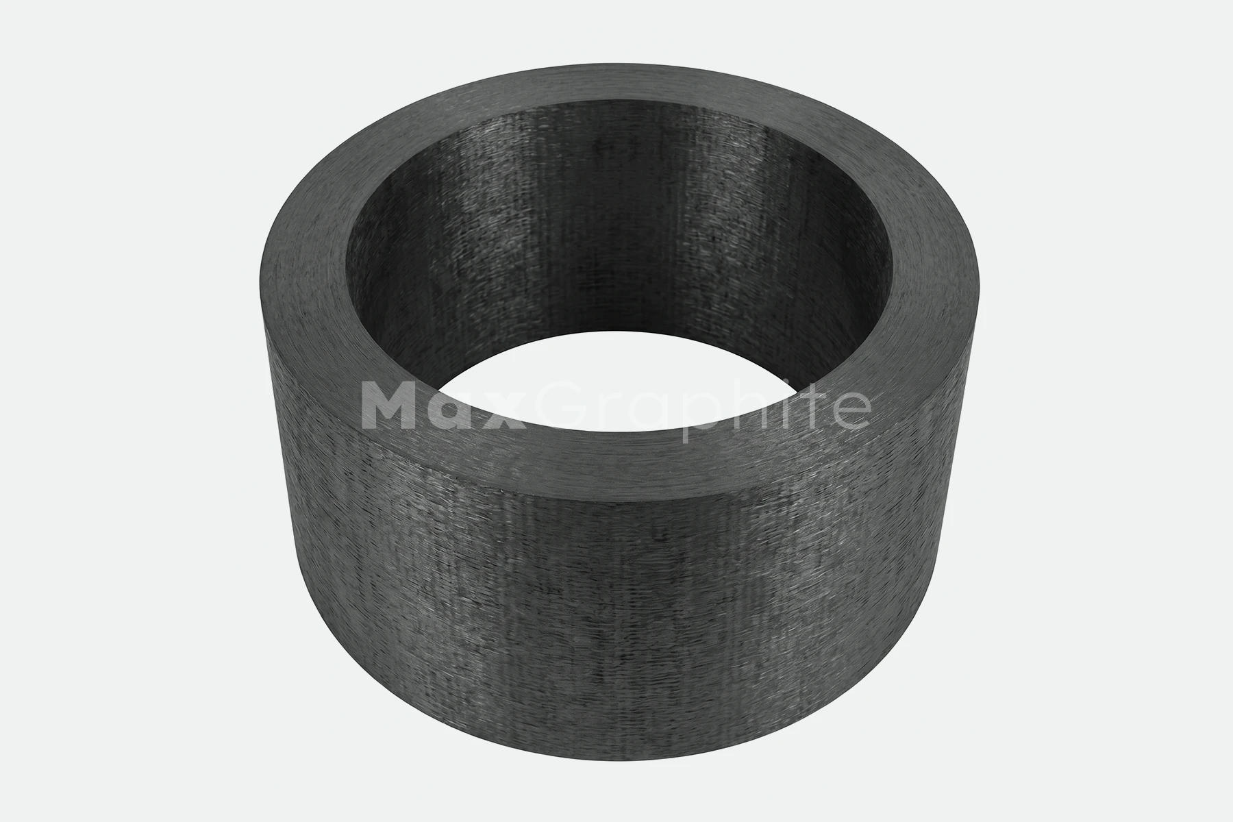
Carbon Carbon Composite Crucibles
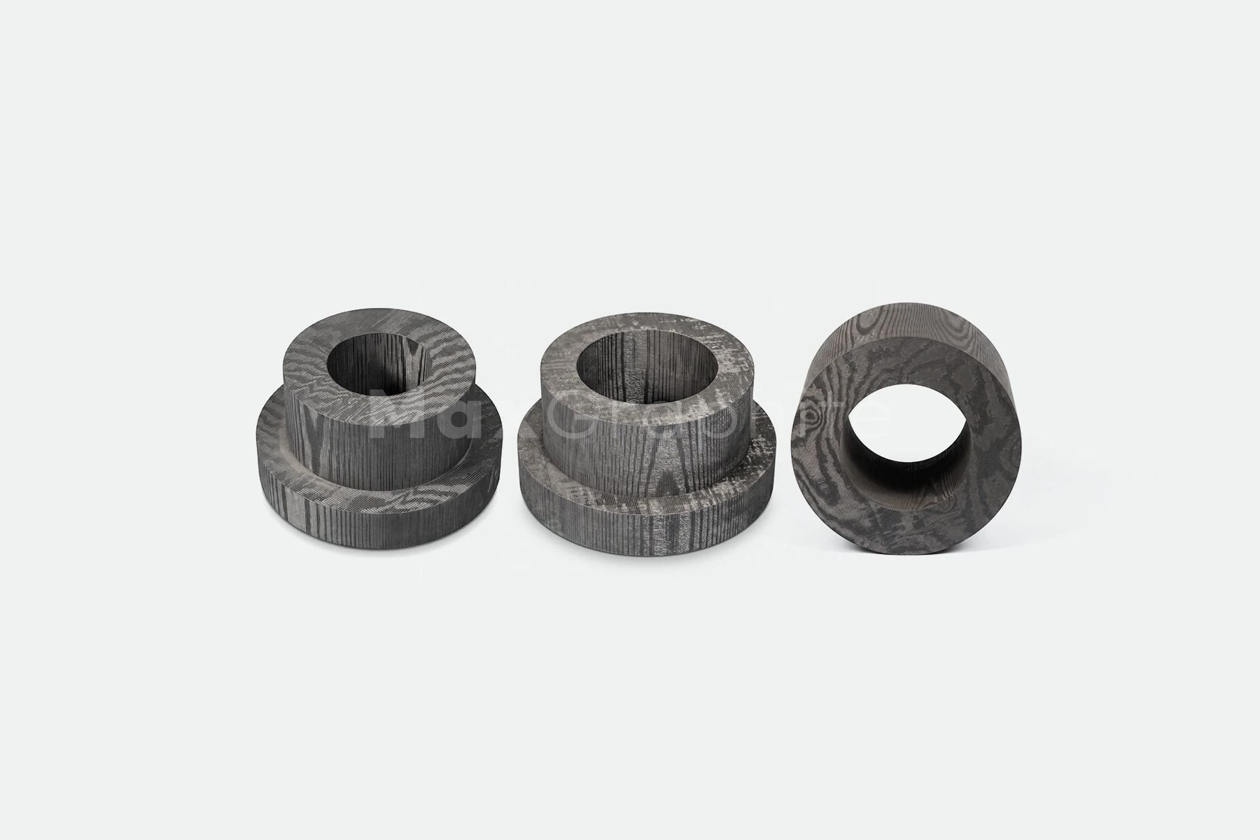
CFC (Carbon-Carbon Composite) Custom Machining
CFC Brake Disc | C/C Brake | Carbon Ceramic Brake
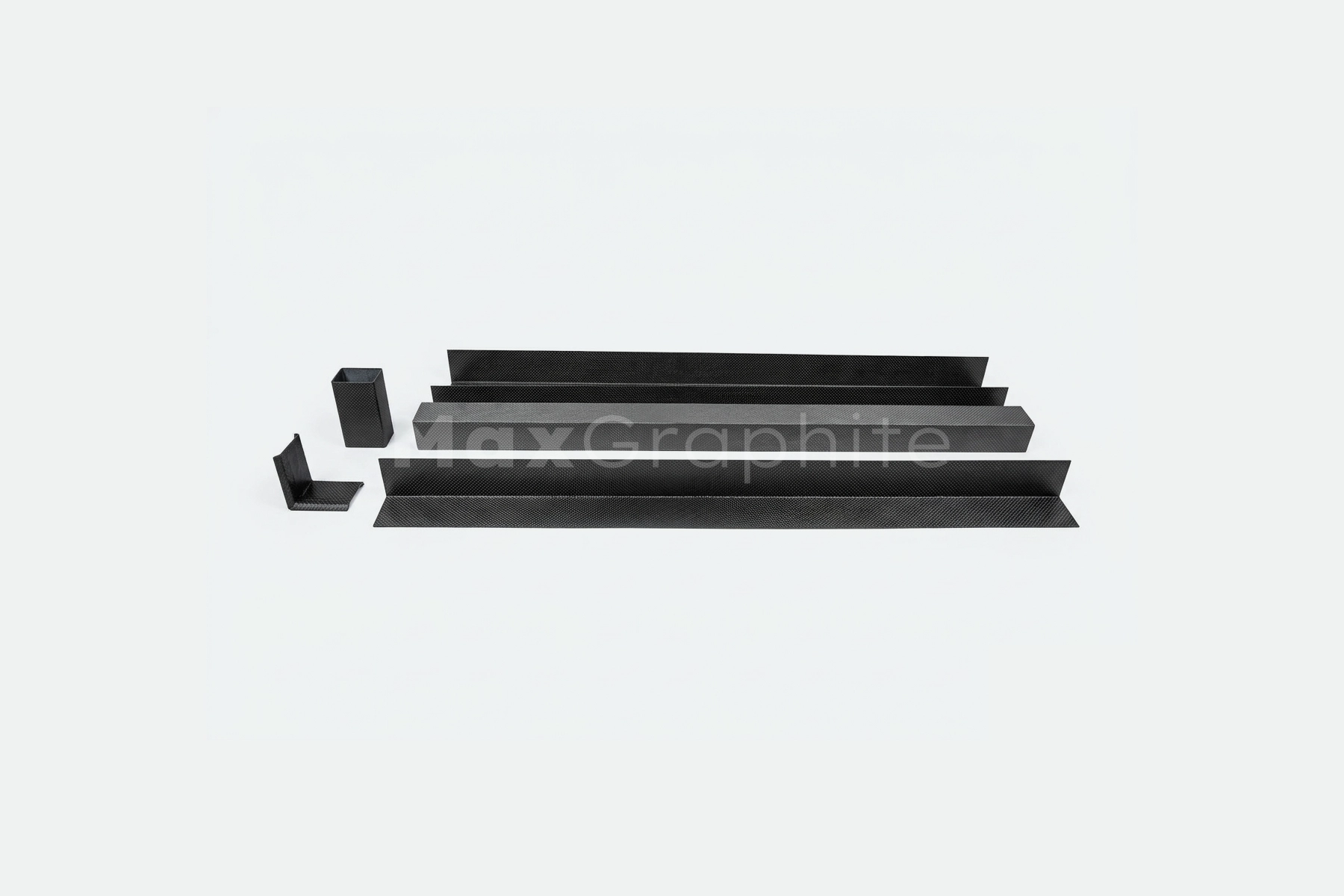
CFC Channels
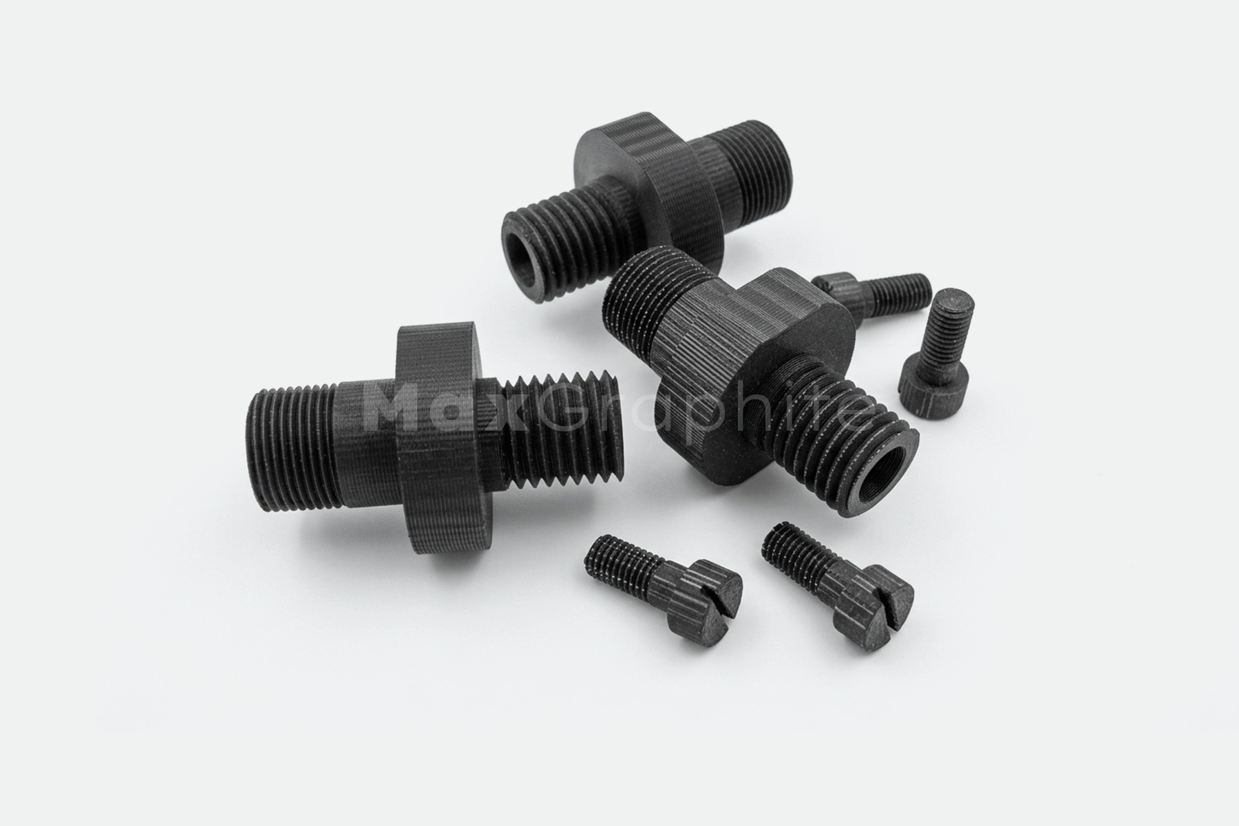
CFC Fastening Elements
CFC Heating Elements
CFC Hot Press Mold Cylinder | C/C Composite Hot Press Mold
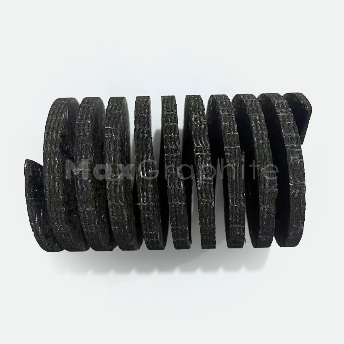
CFC Springs

Graphite & Carbon Components for High-Temperature Furnaces