Carbon Fiber Insulation Cylinders: Choose Between Soft Felt and Rigid Felt
What Separates Soft Felt from Rigid Felt?
Before diving into manufacturing details, it helps to understand the fundamental distinction between these two cylinder types.
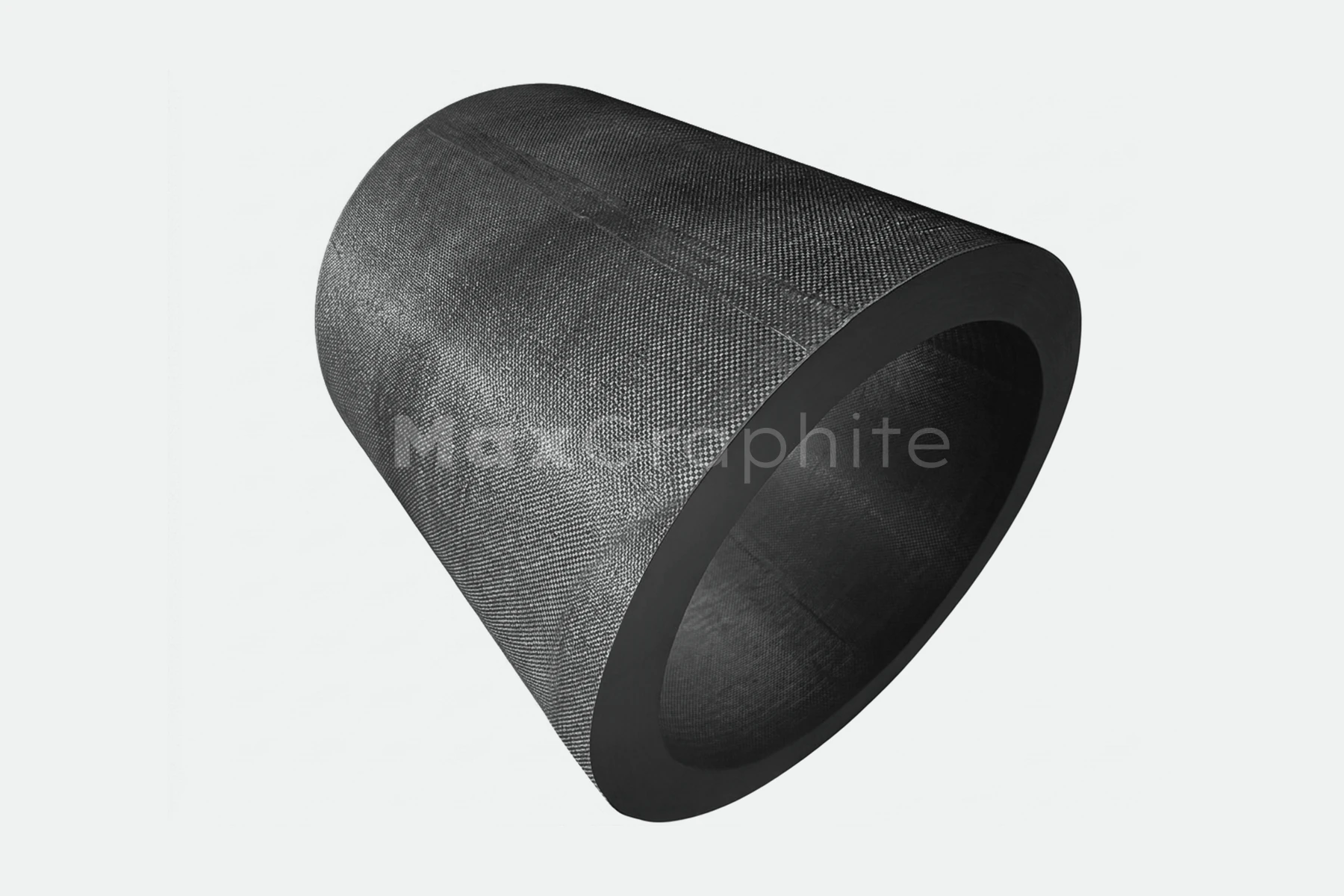
A soft felt cylinder is made from low-density, compressible carbon felt or graphite felt shaped into a tubular form. It retains the flexibility and compressibility of the base felt material and is typically formed by wrapping, splicing, or needle-punching. Soft felt cylinders are well suited to vacuum and inert-atmosphere furnaces where the insulation liner needs to accommodate thermal expansion, allow for assembly tolerances, or be replaced during maintenance. Their primary advantages are low thermal conductivity and light weight. The trade-off is lower mechanical strength and a higher tendency to shed fibers or particles.
A rigid felt cylinder starts from a soft felt preform that is then impregnated with a resin or pitch binder, cured, and carbonized — and in some cases graphitized — to produce a self-supporting, dimensionally stable tube. Alternatively, rigid cylinders can be molded from chopped carbon fiber mixed with a binder system and hot-pressed directly into shape. Rigid felt is the right choice where the application demands structural support, consistent clearance gaps, or resistance to handling and assembly wear.
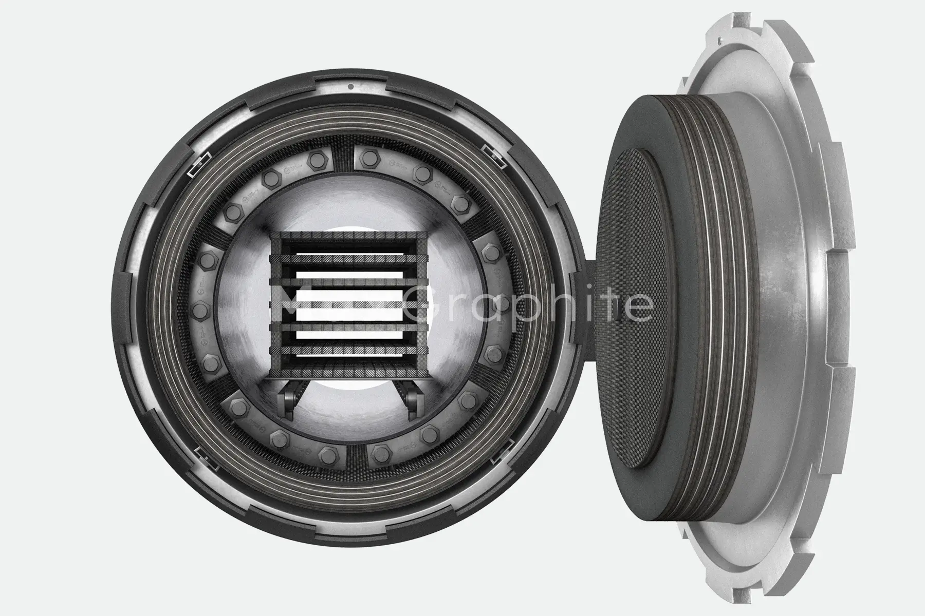
In practice, many high-temperature furnace designs use both types together: a rigid felt inner shell for structural support, surrounded by soft felt layers for maximum thermal resistance.
How Are Soft Felt Cylinders Manufactured?
Producing a soft felt cylinder means converting flat feltstock into a uniform, stable tubular structure while keeping seam integrity andsurface particle shedding under control.
Raw Material Preparation
Manufacturing begins with incoming inspection of the felt stock. Area weight, thickness, ash content, and visual consistency are the primary acceptance criteria. Variation in thickness or density within a single lot will cascade into problems with winding tension control and finished-part dimensional consistency downstream. The felt also typically undergoes a drying step to reduce moisture content and minimize outgassing — a factor that becomes critical in vacuum furnace service.
Three Forming Methods
Winding is the most widely used approach.
Felt is cut to a calculated blank size, wound onto a mandrel, and secured with needle-punching, stitching, cable ties, or localized adhesive bonding. Two variables demand close attention: the blank dimensions must account for material springback, assembly pre-compression, and any downstream thermal shrinkage; and winding tension must remain consistent to avoid density gradients through the cylinder wall.
Splicing is preferred for large-diameter or thick-wall cylinders.
Multiple fan-shaped or strip segments are assembled into a cylinder and the seams are reinforced by needle-punching, stitching, or overlapping. The main risk with splicing is that every seam is a potential thermal bridge and a weak point for particle shedding — so adequate overlap length and a reinforcement layer at each joint are essential.
Direct needle-punching into a cylinder requires dedicated equipment.
Felt layers are needle-punched circumferentially on a cylindrical mold, interlocking the fibers across layers. This method produces the fewest seams and the best structural integrity, but the higher equipment investment makes it most practical for volume production.
Seam Reinforcement and Surface Treatment
Regardless of the forming method, the way seams and edges are finished has a direct impact on service life. Common reinforcement techniques include needle-punching across the seam to interlock fibers, carbon fiber thread stitching for applications that need to be disassembled or resist tearing, overlap wrapping with a thin felt band to reduce edge fiber shedding, and localized adhesive bonding. For vacuum or high-temperature service, any adhesive system must be a verified low-outgassing formulation.
Some applications also call for a carbon–carbon composite overwrap on the cylinder’s outer surface. This layer improves abrasion resistance, reduces loose fiber release, and makes assembly easier.
Common Defects in Soft Felt Cylinders
The most frequent quality issues in production include uneven thickness or density (usually caused by inconsistent winding tension or cutting errors), seam cracking or lifting (from insufficient overlap or sparse stitching), excessive particle shedding (from untrimmed edges or untreated surfaces), and post-assembly sagging (when felt density is too low or pre-compression is inadequate). A practical takeaway: improving seam engineering — overlap length, needle-punch density, edge finishing — typically does more for soft felt cylinder yield than simply specifying a heavier felt grade.
How Are Rigid Felt Cylinders Manufactured?
Rigid felt cylinder production is considerably more complex than soft felt, involving chemical impregnation, high-temperature heat treatment, and tighter process windows at every stage. Two main manufacturing routes are used, depending on fiber length and forming approach.
Route 1: Impregnation and Carbonization of Soft Felt Preforms
This is the most widely used production route in industry. The underlying logic is straightforward: form a soft felt tube, saturate it with a resin or pitch binder to make it rigid, then carbonize the binder at high temperature to create a stiff carbon matrix. The full sequence involves the following stages.
Preforming. Soft felt is shaped into a near-net-shape cylinder blank and fixed on a mandrel.
Impregnation. This is one of the most critical steps in the entire process chain. Phenolic resin is the most common binder in industrial practice; pitch-based systems are also used depending on the target performance profile. Vacuum impregnation — evacuating the blank first, then introducing the resin under pressure — gives the deepest and most uniform penetration. Atmospheric impregnation or brush application is reserved for thin sections or less demanding specifications. The resin’s solids content, viscosity, and temperature all govern how deeply and evenly it penetrates the felt. Weight pickup after impregnation determines the final density and strength of the part. Poor penetration uniformity leads to density differences between the inner and outer walls, which in turn cause cracking or warping during carbonization.
Draining and pre-pressing. After impregnation, excess resin is removed and the blank is pressed in a forming die to reach the target density. Controlled pressure and hold time are essential to achieve uniform resin distribution.
Curing. A staged temperature ramp prevents the exothermic resin cure from generating internal cracking or blistering. The cure endpoint can be monitored through mass stability or controlled against an established process curve.
Carbonization. This step is the make-or-break point for rigid felt quality. Performed under inert atmosphere (nitrogen or argon) or vacuum, it converts the resin or pitch binder into carbon, forming a rigid skeletal structure. Significant volumetric shrinkage accompanies carbonization. Heating too fast risks cracking, blistering, or delamination. For thick-walled parts, volatile byproducts must have clear exit paths to prevent internal pressure buildup. Fixturing and support design must prevent the cylinder from deforming or going out of round during the thermal cycle.
Graphitization (optional). Where the application demands higher service temperatures, lower electrical resistivity, or improved structural stability, the carbonized part can undergo further heat treatment — typically above 2,000°C.
Machining and cleaning. Final operations include turning the inner and outer diameters, facing the ends, chamfering, and cutting any required slots or holes. Dust control during machining is important — carbon dust is extremely fine. Dimensional tolerances, roundness, concentricity, and surface particle shedding grade are all verified at this stage. For vacuum or semiconductor applications, the part also goes through clean-room blowdown and vacuum bake-out, with residual particle counts and volatile levels (TML/CVCM where applicable) checked against specification.
Route 2: Chopped-Fiber Molding
The second route suits applications that require tighter part-to-part consistency, fewer seams, or complex cross-sectional profiles — at the cost of higher tooling and equipment investment.
Chopped carbon fibers are blended with optional carbon or graphite powder and a resin or pitch binder, then formed into a preform through either a wet-laying process (similar to papermaking) or a dry air-laid / carded web process. The preform is then hot-pressed or cold-pressed in a mold to achieve the target shape and density, followed by curing, carbonization or graphitization, and final machining. Fiber length distribution, formulation ratios, and mix homogeneity are critical at the front end; for the wet route, preform moisture content adds another variable. Heat treatment and post-machining requirements mirror those of Route 1.
Soft Felt or Rigid Felt? A Selection Framework
Choosing between the two types requires weighing several interdependent factors. Here is how they compare across the dimensions that matter most in furnace insulation design.
Quality Control: Key Inspection Points from Raw Material to Finished Part
Whether the product is a soft felt or rigid felt cylinder, a robust quality system must span incoming materials, in-process checks, and final inspection. The following areas are the ones most likely to drive batch-to-batch variation and end-user complaints.
Incoming Material Inspection
Felt stock is checked for area weight, thickness, ash content, and surface defects on a lot-by-lot basis. For rigid felt production, the resin system’s solids content, viscosity, and volatile fraction are also mandatory incoming checks, since they directly affect impregnation process stability.
In-Process Inspection
For soft felt cylinders, the focus is on cut-blank dimensional accuracy, winding tension records, and first-article verification of the seam structure. For rigid felt cylinders, the critical in-process data points are weight pickup after impregnation, density after pre-pressing, mass stability after curing, and crack or deformation checks after carbonization.
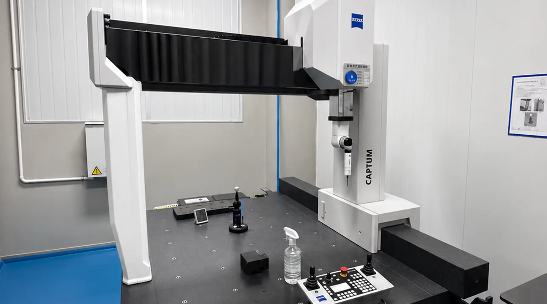
Finished Part Inspection
Dimensional verification covers inner diameter, outer diameter, height, roundness, concentricity, and end-face flatness. Physical property testing differs by type: soft felt cylinders are evaluated for density, compressive strength, and springback; rigid felt cylinders for density, flexural strength, and compressive strength. Cleanliness is assessed through wipe or vibration-shedding tests to quantify particle levels. For vacuum applications, outgassing testing to the relevant customer or internal standard rounds out the inspection protocol.
Let's talk
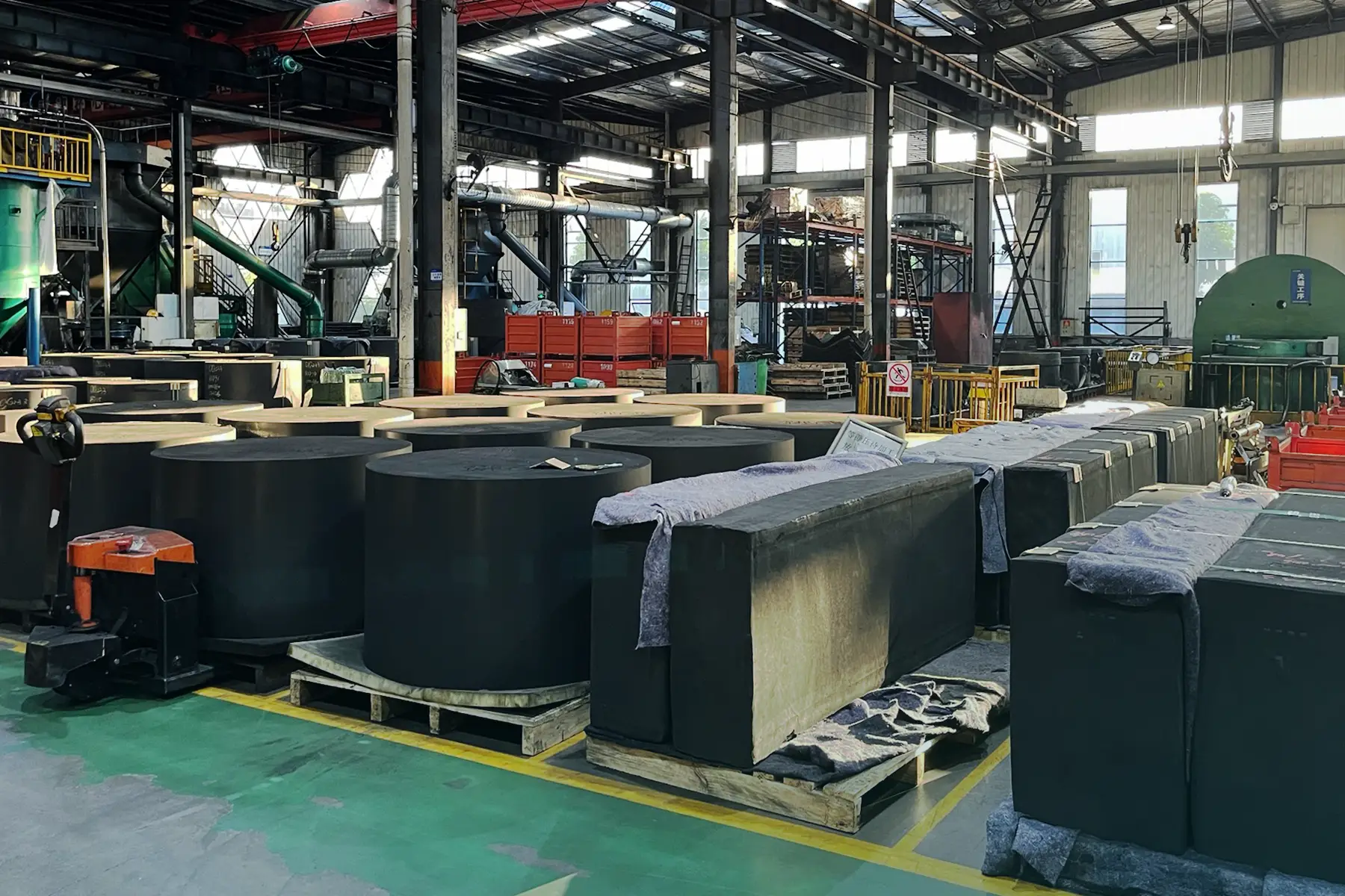
Max Graphite manufactures carbon fiber insulation components — including soft felt and rigid felt cylinders — to tolerances that meet or exceed recognized industry benchmarks. If you are specifying insulation for a new furnace build or evaluating alternatives for an existing system, our technical team can help you match the right material and construction to your operating conditions.
Why Dimensional Accuracy in Machined Graphite Components Matters — and How It's Verified
Max Graphite: Vertically Integrated Graphite Manufacturer in China