Graphite Components for Thermal Fields: The Coupling with Carbon Felt
What heat-transfer modes actually dominate inside a hot zone?
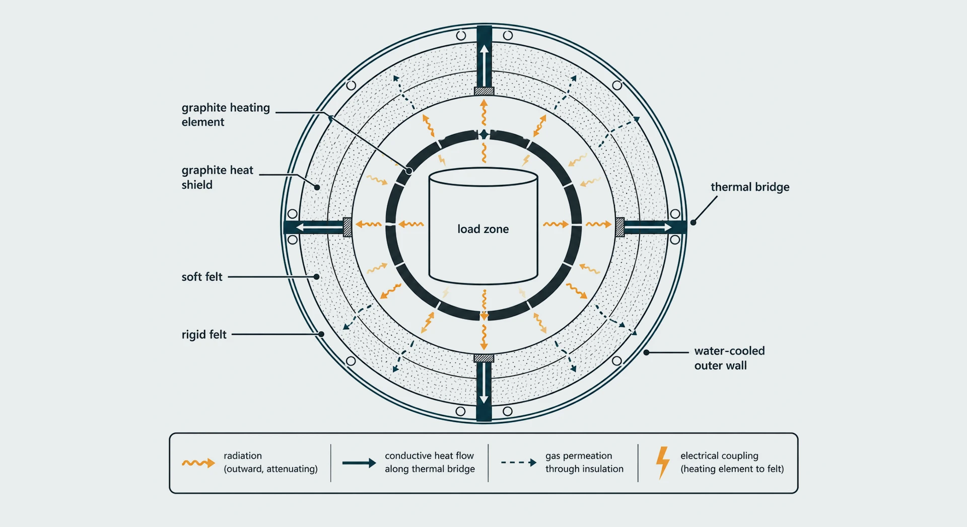
Most thermal-field equipment operates in vacuum or low-pressure inert atmosphere. Under those conditions, gas density is low and flow is weak, so convective heat transfer contributes very little. Only two mechanisms drive the temperature field: radiation and conduction.
This fact has a consequence that is often missed at the specification stage. The thermal conductivity values that dominate product data sheets describe only half the story. In vacuum service, the surface emissivity of graphite and the optical thickness of carbon felt matter as much as conductivity — and sometimes more.
Once this is internalized, a lot of furnace behavior makes sense. Why does swapping a graphite heater geometry change cold-wall temperature even with the same felt thickness? Why does a thin graphite foil applied to the hot face of rigid felt cut radiation losses noticeably? Why does assembly torque on a soft-felt liner influence efficiency? All three are coupling effects.
Radiation coupling: graphite sets the boundary, felt attenuates the field
Graphite as a radiation boundary
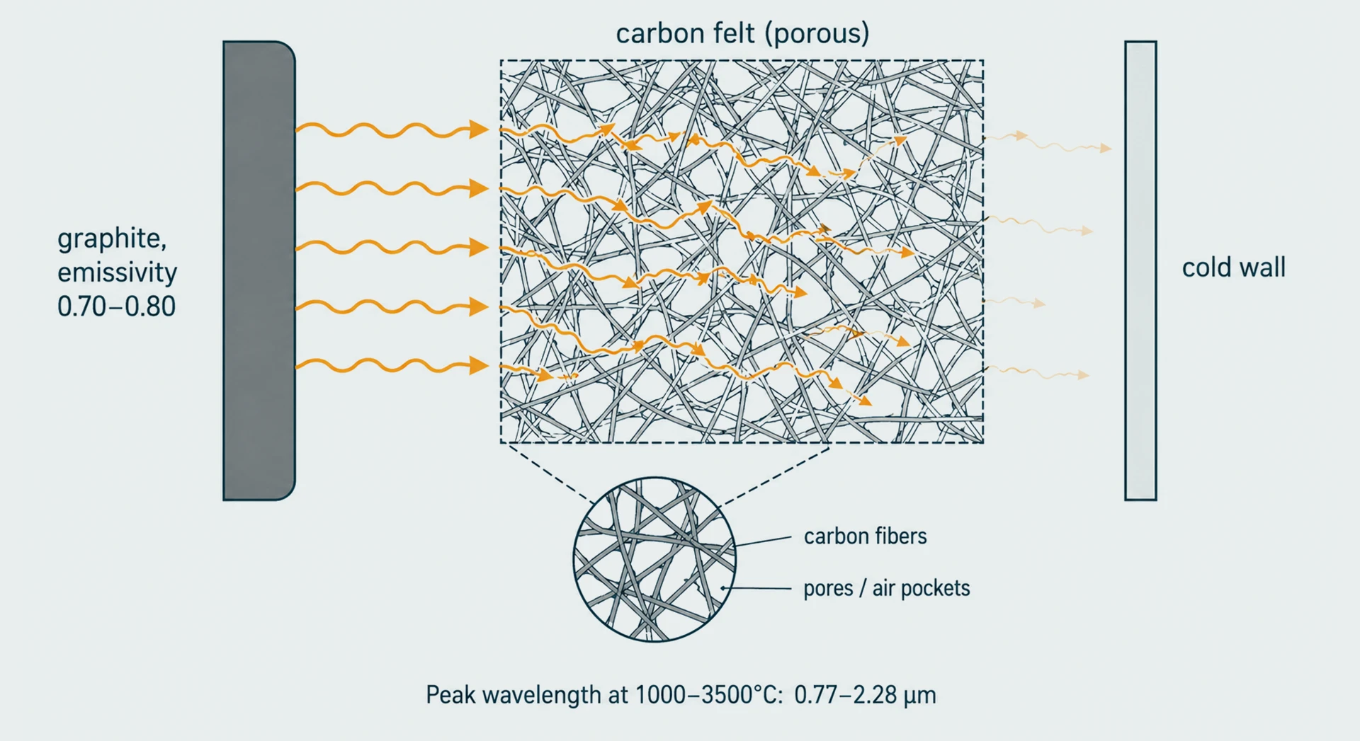
Engineers typically treat graphite as a high-emissivity gray body. Standard reference tables give the total emissivity of graphite across 0–3,600 °C as roughly 0.70 to 0.80, depending on surface condition — pressed, machined, and polished surfaces sit at different points within the range.
The implications:
• A graphite heating element radiates both inward to the load and outward to the cold wall.
• Graphite heat shields, supports, and flow guides are nodes in the radiative network, not passive structures.
• Any change to graphite surface condition — deposition, ash buildup, oxidation, coating wear — shifts emissivity and drifts the temperature field over service life.
Carbon felt as a participating medium
Carbon felt is not a passive insulation blanket. Its pore structure and fiber diameter determine how radiation propagates through it: by absorption, scattering, and re-emission.
The dominant wavelength of thermal radiation shifts with temperature, following Wien's displacement law. In the 1,000–3,500 °C range typical of thermal-field service, peak radiation wavelengths fall between 0.77 and 2.28 µm. Felt structures whose pore size and fiber diameter scatter or absorb efficiently in this band raise the radiative attenuation coefficient and lower the effective radiative conductivity.
This is what graphite-felt radiation coupling actually means: graphite determines the intensity and geometry of the radiation field; felt determines how that field propagates and decays through the insulation layer.Designing one without the other leaves performance on the table.
Why does compressing soft felt cut both ways?
Soft carbon felt is a low-density, high-porosity material. When it is compressed during assembly, two things happen at the same time:
1. Solid-to-solid fiber contact increases, equivalent density rises, and solid-phase thermal conduction goes up.
2. Optical thickness rises, the material becomes more opaque to radiation, and radiative transmission drops.
These two effects pull in opposite directions. Compressing felt suppresses radiative leakage, but raises solid conduction. The net thermal resistance can move either way, depending on initial density, fiber geometry, and how hard the felt is pressed.
Rigid felt sidesteps the variability — it is bonded and pre-compressed during manufacturing, so thermal parameters are fixed and repeatable. But it gives up the geometric flexibility of soft felt around complex shapes. The choice between the two is, at its core, a choice between assembly flexibility and thermal-resistance repeatability.
Thermal bridges: graphite's strength is also its liability
Graphite conducts heat well. That is a feature when uniform temperature is wanted across a heating element or susceptor — heat spreads in-plane and circumferentially, smoothing hot spots. It becomes a liability wherever a graphite structure connects the hot zone to a cooler boundary: supports, fasteners, current-carrying leads, structural frames. Each forms a high-conductivity thermal bridge that bypasses the insulation.
Bridge location, cross-section, and length often matter more to real-world heat loss than felt thickness does.
How much does geometry change the real thermal-resistance network?
Thermal-field insulation is rarely a single block of material. It is a multilayer assembly, and a handful of geometric rules dominate real performance:
• Stagger the joints. Adjacent felt layers should never share a seam plane. A through-thickness gap is a direct radiation and gas-permeation channel.
• Build resistance through layer count. Felt is commonly stacked in 6 mm or 12 mm layers; rigid board panels often run around 25 mm. Total resistance is built up by adding layers, not by specifying thicker custom slabs.
• Treat corners, penetrations, and observation ports as design problems. Thermocouple feedthroughs, electrode passages, and viewports are where local hot spots and cold-wall hot zones originate.
Two assemblies built from identical materials can show effective conductivities that differ by several times based purely on these details. Geometry is part of the coupling, not a fabrication-floor afterthought.
Why isostatic graphite is the default for hot-zone components
Once the coupling picture is clear, the manufacturing question reverses. Instead of asking which graphite is best, the question becomes: which graphite production route delivers the surface and bulk properties the coupled system needs?
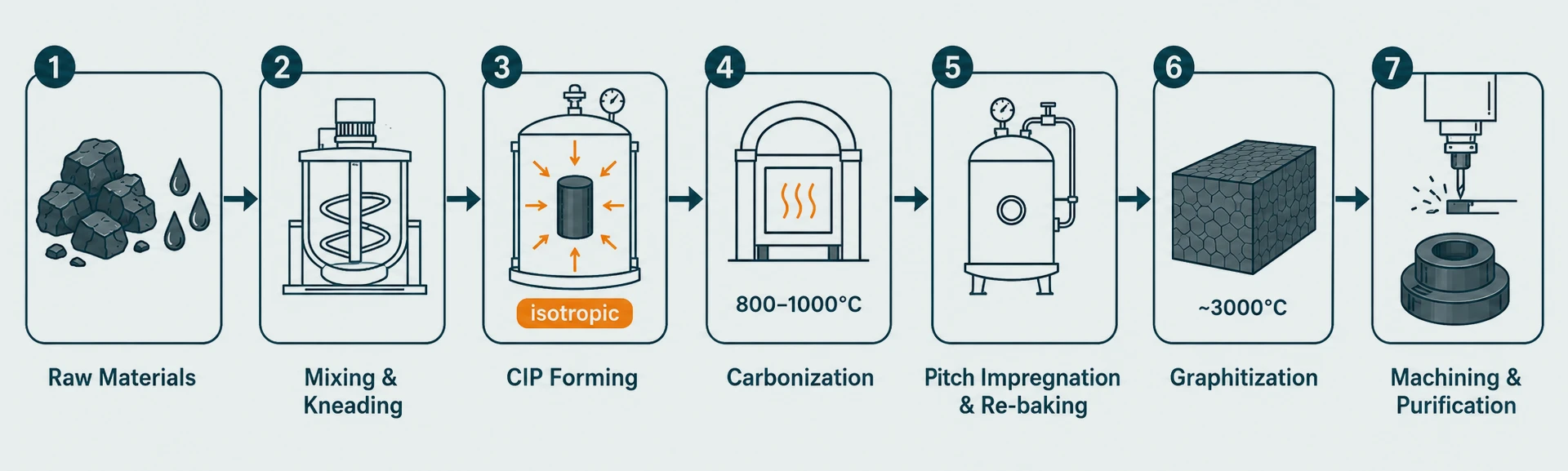
The synthetic graphite process used for hot-zone components typically runs as follows:
1. Raw materials and formulation. Petroleum coke or needle coke serves as filler; coal tar pitch is the binder. Calcination, milling, and particle classification set grain structure.
2. Mixing and kneading. Milled coke and pitch are combined in a heated mixer; molten pitch coats the coke particles and penetrates their pore structure to form a moldable mass.
3. Forming. Three main routes — extrusion (electrodes, rods), die-molding or vibration molding(large blocks), and cold isostatic pressing (CIP).
4. Carbonization. The green body is baked under inert atmosphere, typically at 800–1,000 °C, converting pitch into binder coke with significant mass loss and outgassing.
5. Pitch impregnation and re-baking. The porous carbon body is impregnated with pitch under vacuum or pressure, then re-baked, raising density and strength.
6. Graphitization. Material is heated to roughly 3,000 °C in electric furnaces, converting amorphous carbon into a graphitic crystal structure. This step defines the performance ceiling.
7. Finishing. Machining to final geometry, plus optional purification or surface coating depending on application.
Among the three forming routes, CIP produces the most isotropic, finest-grain microstructure. Isotropy matters because thermal expansion, electrical resistivity, and thermal conductivity converge across all three axes — which translates directly into uniform heating across an element, stable radiative geometry on a heat shield, and dimensional consistency on a support. Extrusion has higher throughput but introduces grain orientation that becomes a liability wherever temperature uniformity is the goal.
A practical consequence: graphite heating elements are almost never formed to their final shape during the carbon-to-graphite process.Manufacturers produce blocks or plates meeting electrical, thermal, and purity targets, then precision-machine those into element geometries. The CIP route makes this “block first, machine second” workflow the practical standard for high-performance heaters.
Soft felt, rigid felt, and surface treatment
Carbon fiber insulation divides into two families based on processing:
• Soft felt —uncompacted, low-density fiber batts. Flexible during assembly, but thermal resistance varies with compression.
• Rigid felt —bonded and pre-compressed during manufacturing, sometimes with a surface lamination. Thermal parameters are fixed; geometry is stable.
Choosing between the two at the design stage is really a choice between assembly flexibility and thermal-resistance repeatability. There is no universally correct answer — it depends on whether the hot-zone geometry tolerates a fixed-shape liner or requires conformability.
Rigid felt is often paired with a hot-face treatment: a graphite foil overlay, a carbon-cloth covering, or a thin coating. The purpose is to lower the effective emissivity of the hot face, raise the fraction of radiation reflected back into the heated zone, and protect the felt from process gas erosion or quench-gas flow.Published reports indicate that interleaving foil layers between rigid felt sheets can yield a 5% to 35% improvement in insulation effectiveness — a direct coupling-based gain, using the foil's radiative reflectance to reinforce the felt's intrinsic attenuation.
Graphite foil and SiC coatings: different materials, different process logic
The manufacturing route for graphite foil has almost nothing in common with synthetic graphite. It comes from natural graphite through intercalation, exfoliation, and calendering:
1. Strong oxidizing acids intercalate between graphite layers, forming a graphite intercalation compound (GIC).
2. Washing yields expandable graphite.
3. Rapid heating drives layer separation, producing“worm-like” exfoliated graphite.
4. Calendering rolls the exfoliated material into thin foil.
The value of graphite foil lies in flexibility and cuttability. It serves as gasket and seal material in some applications, and as an interlayer radiation barrier inside rigid-felt assemblies in others.
Silicon carbide (SiC) coatings belong to a different process category again. In high-purity or high-erosion service — SiC crystal growth, epitaxy, certain CVD processes — isostatic graphite surfaces are coated with a thin SiC layer via chemical vapor deposition, typically above 1,200 °C. The coating raises corrosion and erosion resistance, extends service life, and reduces graphite-borne contamination. It is not a finishing afterthought: the coating changes surface emissivity and roughness, making it part of the radiation coupling.
Practical selection guidance from the coupling perspective
Translated into design practice, the coupling view yields a few stable rules:
1. Do not evaluate graphite components and carbon felt independently. Define hot-zone targets first — uniformity tolerance, peak temperature, cold-wall limit, outgassing budget — then work backward to the material combination.
2. In vacuum service, give equal weight to emissivity and optical thickness, not just thermal conductivity. These are the parameters most often overlooked at the specification stage.
3. Treat soft-felt compression as a design variable, not a fabrication-floor decision. Fix the compression ratio at the design stage and enforce it through rigid felt, mechanical stops, or framing.
4. Identify thermal-bridge paths on the drawing board. Every support, fastener, lead, and feedthrough has an equivalent heat-loss rating that should be estimated, not discovered.
5. Joint stagger, corner reinforcement, and penetration design produce larger resistance differences than swapping materials. Spend design time on these details.
6. Allow margin for surface drift. Deposition, ash, oxidation, and coating wear shift emissivity over service life. Specify the system so it tolerates the slow-variable drift, not just first-day conditions.
Why vertically integrated manufacturing matters here
Thermal-field performance is a system question, not a single-material question. A vertically integrated manufacturer producing graphite, carbon felt, CFC components, graphite foil, and coatings under one roof carries a structural advantage in coupling-aware design:
• Graphite grain size, purity, and isotropy can be specified against the radiative properties of the matched heat shields and felt.
• Soft- and rigid-felt density, thickness, and surface treatment can be tuned to the emissivity of the graphite parts.
• Assembly schemes, joint stagger, and bridge management can be designed in from the material stage, not added afterward.
Single-material suppliers can only refine within their own product boundary. They cannot reach across the graphite-felt-foil-coating boundary that actually determines hot-zone behavior. That gap is the reason Max Graphite positions itself as a manufacturer from raw material to finished component, rather than as a catalog reseller — the value of thermal-field materials shows up at the system level, and the system level requires all the materials.
That is what Accessible Excellence means in engineering terms: making the system-level matching of high-performance thermal-field materials available beyond the few engineering teams with deep relationships at every link of the supply chain.
Let's talk
Working on a vacuum furnace, crystal-growth reactor, or high-temperature heat treatment system? Talk to our engineering team about graphite, felt, and CFC component selection — from raw material to finished component, under one roof.
Inside the Graphitization Furnace: What Happens to Carbon at 2,400°C
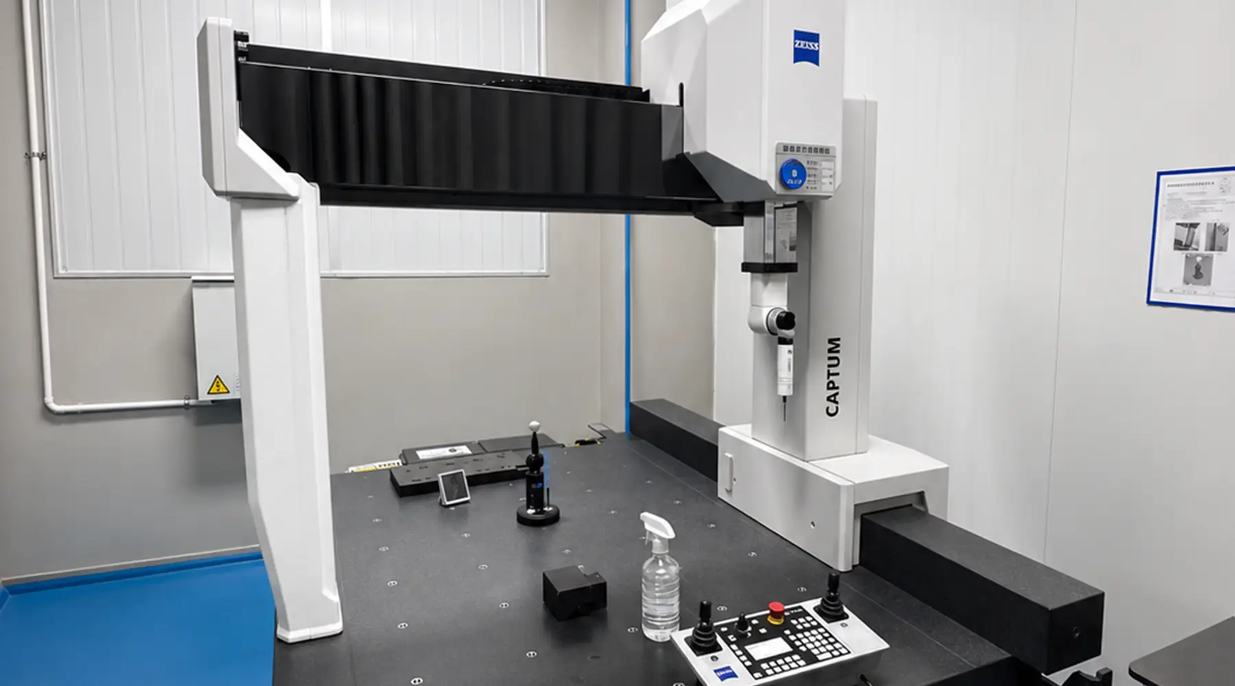
Why Dimensional Accuracy in Machined Graphite Components Matters — and How It's Verified